17 Years Factory 26″ Industrial rubber glove-rough finish to Algeria Manufacturers
Short Description:
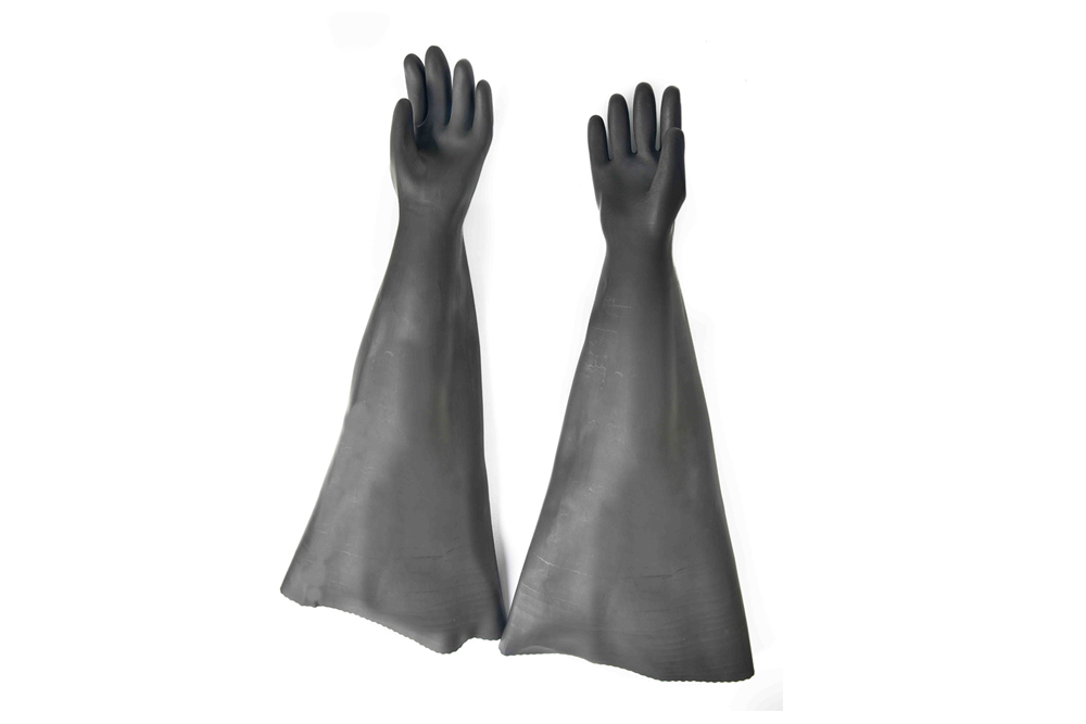
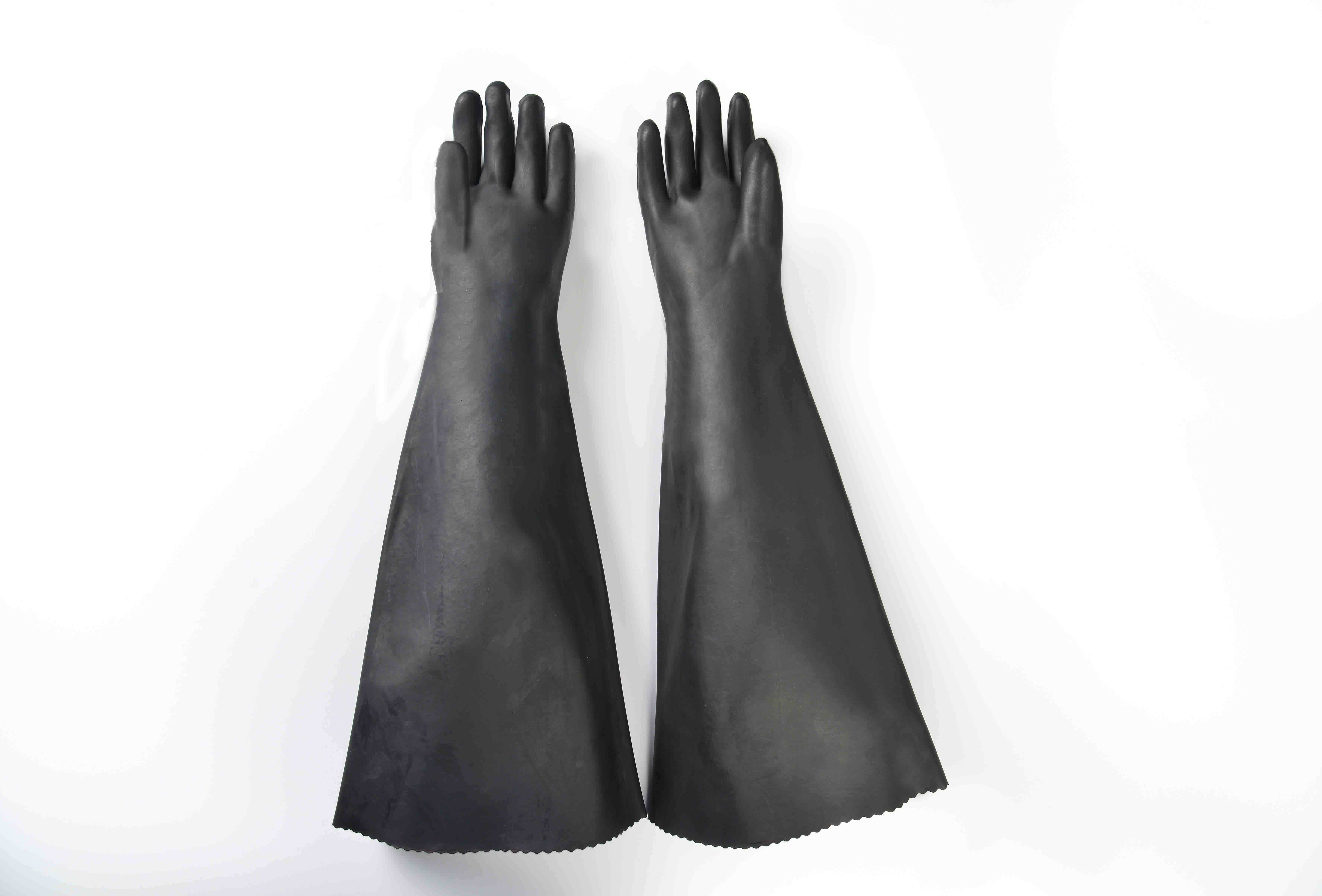
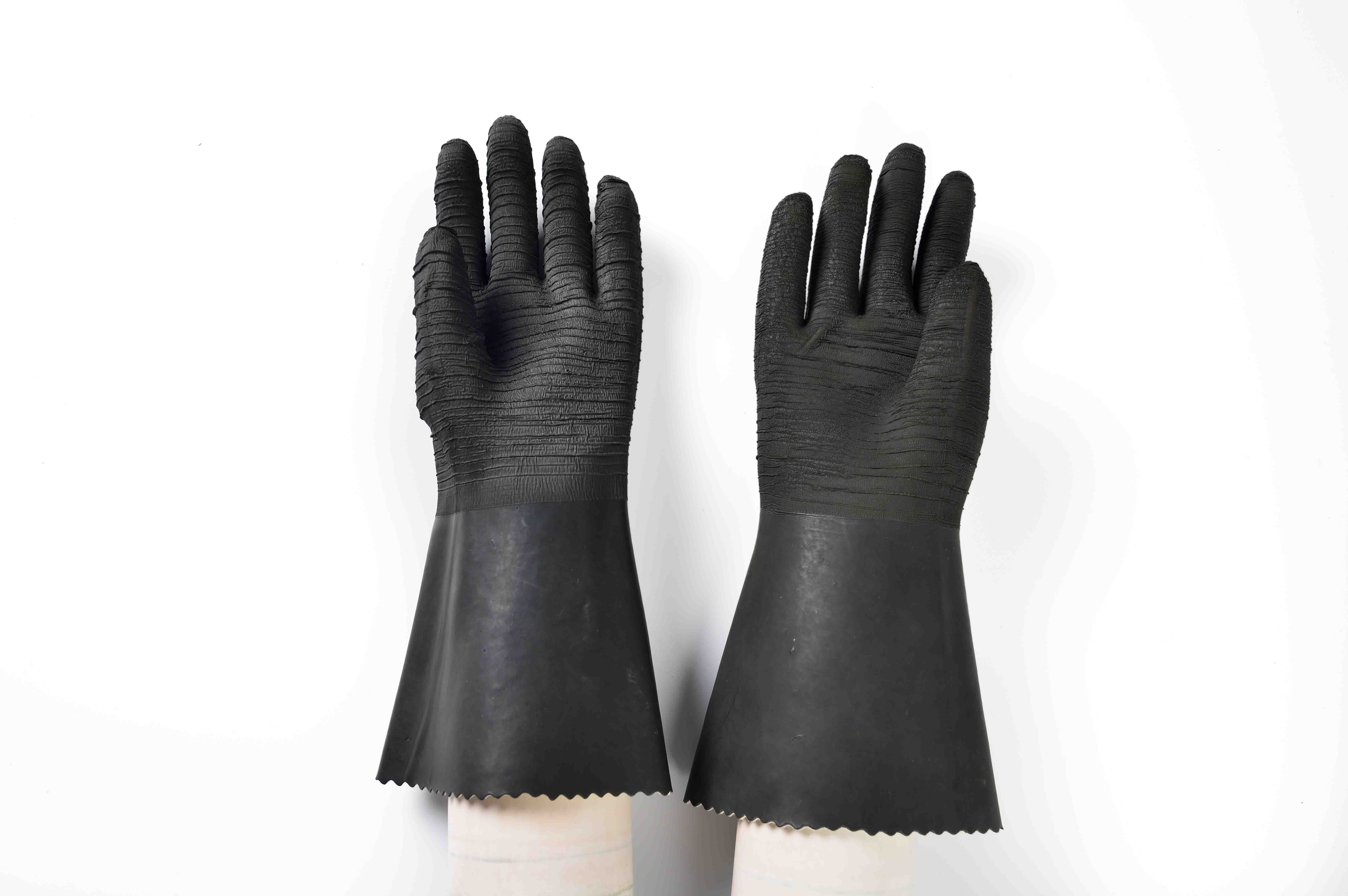
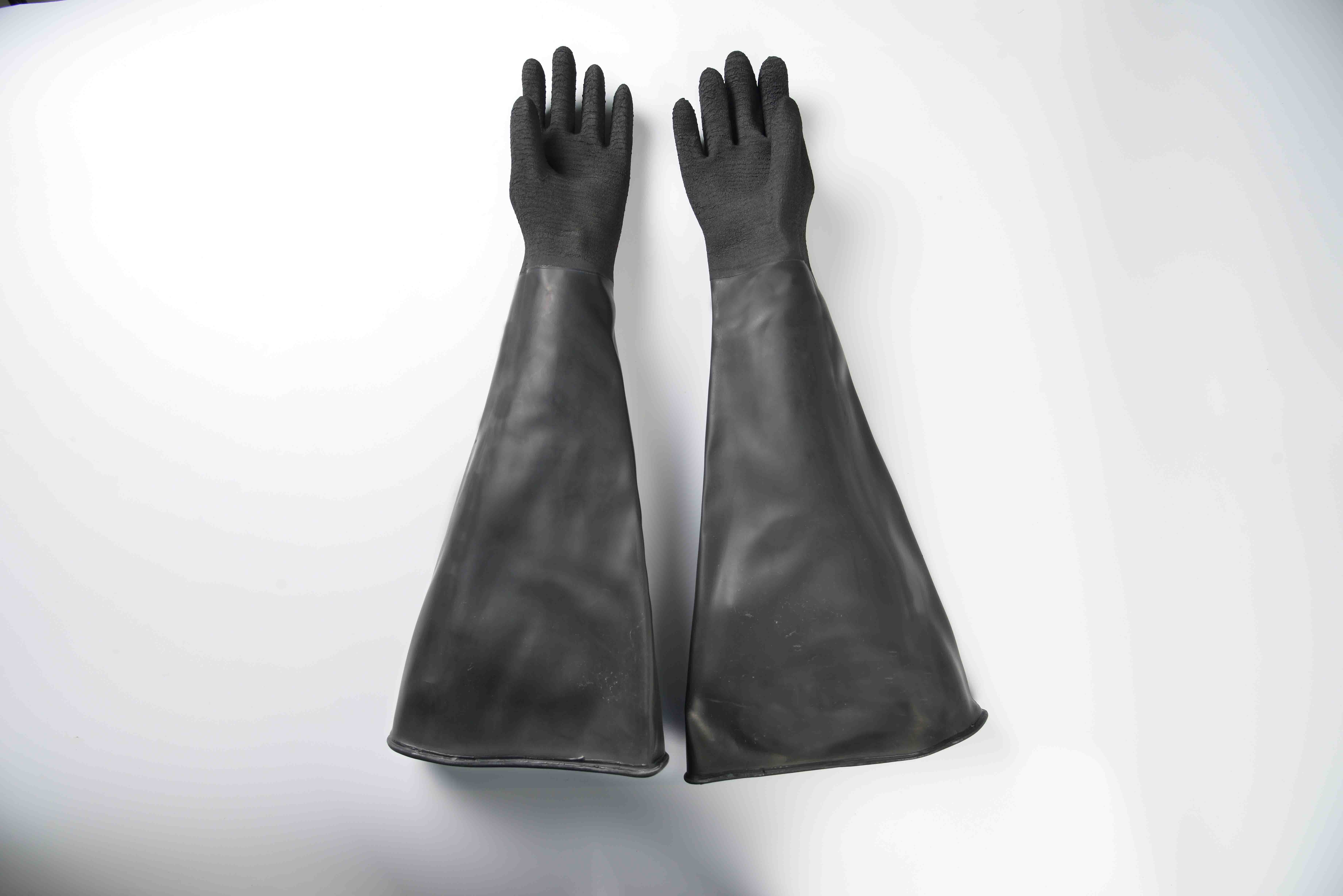
26”length (65-67cm), black, rough finish, seamless, no cotton lining, left/right hand, 700g/pair, cuff perimeter:61cm, double layer thickness:2.2mm. 50 pairs/case, carton size: 74*36*44cm. Net weight: 35kg/case, gross weight: 37kg/case. It can be suitable used with sand blasting machine operation.
Product Detail
FAQ
Product Tags
We always stick to the principle "Quality First, Prestige Supreme". We are fully committed to providing our clients with competitively priced quality products, prompt delivery and professional service 17 Years Factory 26″ Industrial rubber glove-rough finish to Algeria Manufacturers, We sincerely welcome domestic and foreign merchants who calls, letters asking, or to plants to negotiate, we will offer you quality products and the most enthusiastic service,We look forward to your visit and your cooperation
26”length (65-67cm), black, rough finish, seamless, no cotton lining, left/right hand, 700g/pair, cuff perimeter:61cm, double layer thickness:2.2mm. 50 pairs/case, carton size: 74*36*44cm. Net weight: 35kg/case, gross weight: 37kg/case. It can be suitable used with sand blasting machine operation.
FAQ Content
http://www.manner-model.com.pl/en/38-gals-s-footwear/54-sandals/fifty five-dope/boots-patent-leather-heel-15cm-producer-poland-roz-36-forty seven-2016-01-21–details
http://www.manner-model.com.pl/38-obuwie-damskie/54-sandaly/fifty five-lakier/sandaly-z-lakierku-obcas-15cm-producent-polska-roz-36-forty seven-details
http://www.trend-design and style.com.pl/prod.php?lang=pl&fs=1173
http://www.trend-design and style.com.pl/prod.php?lang=en&fs=1173